Safety Factors
The following safety factors are intended as general guidelines for determining maximum design loads and stresses in Indiana Limestone, and in anchors and supports for Indiana Limestone. These values represent the minimum safety factors which the Institute considers to be good practice for most applications. The designer must always use judgment based on the specific application to determine proper safety factors. Proper safety factors may be more conservative than the values suggested in this bulletin, depending on the specific condition under consideration.
The physical properties of Indiana Limestone should be determined by lab test for the specific stone to be furnished. In lieu of lab tests, the minimum properties, as listed in the Indiana Limestone Handbook performance tables, may be used to determine maximum allowable working stresses.
STONE STRESSES
-
Gravity Loads
Stone stressed in bending due to gravity loads: Use not less than 8 to 1 safety factor applied to the modulus of rupture to determine maximum allowable extreme fiber stresses.
-
Lateral Loads
Stone stressed in bending due to lateral loads (wind loads or seismic loads): Use not less than 8 to 1 safety factor applied to the modulus of rupture to determine maximum allowable extreme fiber stresses. A stress increase of 1/3 is permissible when the building code for the project permits this increase for other building materials. This provides a safety factor of not less than 6 to 1 for lateral load bending stresses.
-
Combined Gravity and Lateral Loads
Combined stone bending stresses due to gravity loads and lateral loads: Use not less than 8 to 1 safety factor applied to the modulus of rupture to determine maximum allowable extreme fiber stresses.
- shear
- compression
- pure tension (axial loads)
1. Stress Modes—Bending
2. Stress Mode
Use not less than 8 to 1 safety factor applied to the ultimate test value (at failure) to determine maximum allowable working stresses.
3. Stone Stresses at Connection Points (Anchors)
For connection devices, the maximum allowable design load at the anchorage point of the device into the stone shall not exceed 25% of the failure load of the stone as determined by relevant tests performed on Indiana Limestone.
Anchoring devices subjected to both tension and shear shall be designed in accordance with the following interaction formula:
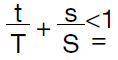
-
t = applied tension load
T= allowable tension load
s = applied shear load
S= allowable shear load
The minimum depth of anchor embedment, the minimum center to center distance and the minimum edge distance shall be in accordance with the manufacturers’ recommendations (expansion bolts and similar anchors).
It is good practice to install expansion bolts to an embedment depth greater than the recommended minimum depth. This results in substantial increases in the factor of safety with a negligible cost effect.
4. Stone Stresses at Post Tension Anchor Plates
These safety factors apply to stone stresses at post tension anchor plates which have been epoxied to the stone bearing surface to assure complete uniform pressure distribution. Tendon loads shall be precisely applied with specialized equipment by personnel experienced in the proper tensioning procedures.
Stone Compression Stress:
Stone Shear Stress:
Use not less than 6 to 1 safety factor applied to the ultimate test values (at failure) to determine maximum allowable working stresses.
STEEL STRESSES—CONNECTIONS
5. Stress Mode—Gravity Connections
Maximum allowable bending stresses at gravity supports shall not exceed 50% of the yield stress (18,000 for A36 steel). All other allowable stress to be in accordance with AISC Manual of Steel Construction.
6. Stress Mode—Retention Connection (Wind loads and seismic loads)
All allowable stresses to be in accordance with AISC Manual of Steel Construction.
7. Stress Mode—Frames for Preassembly of Limestone Panels
All allowable stresses to be in accordance with AISC Manual of Steel Construction.
8. Stress Mode—Secondary Framing (Wind girders, braces, hangers)
All allowable stresses to be in accordance with AISC Manual of Steel Construction.
9. Stress Mode—Stainless Steel Anchors and Devices Contained within the Stone
Maximum allowable stresses shall be in accordance with Stainless Steel Stone Anchors published by the American Iron and Steel Institute (1975), except that the maximum design loads shall not exceed the values defined in Paragraph 3, Stone Stresses at Connection Points (Anchors).
10. Stress Mode—Post Tensioning Tendons and Hardware
Allowable stresses to be in accordance with recommendations of the tensioning materials supplier for the system to be used.